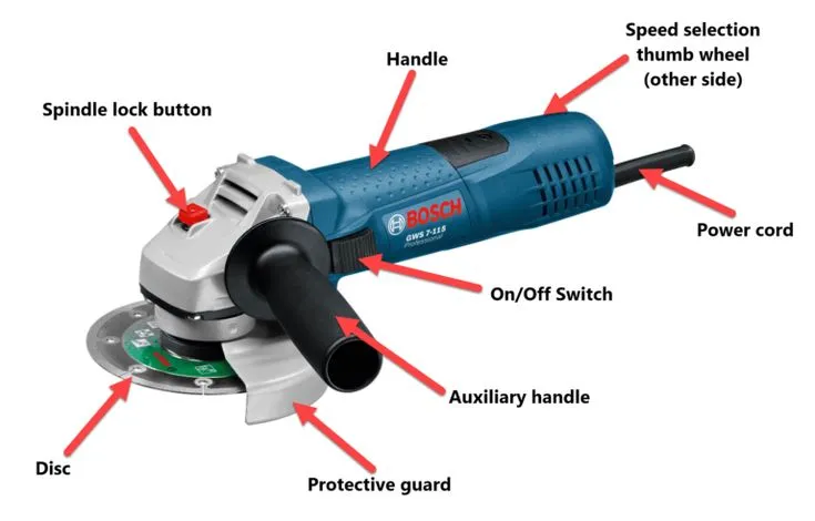
An angle grinder combines an electric motor, a right-angle gearbox, a spindle and an accessory mounting system. Handles provide control; a suitable guard limits exposure to the rotating accessory. Switches, cooling passages and optional electronics support operation.
Knowing these parts helps buyers specify a tool, operators describe a fault, and distributors order correct spares. This guide explains their relationship. For model selection, use our separate angle grinder buying guide.
Read the component map before ordering parts
Start with the model number. Similar-looking grinders can use different guards, bearings, switches and mounting hardware. An illustration explains general anatomy; only a model-specific exploded drawing identifies replacement parts.
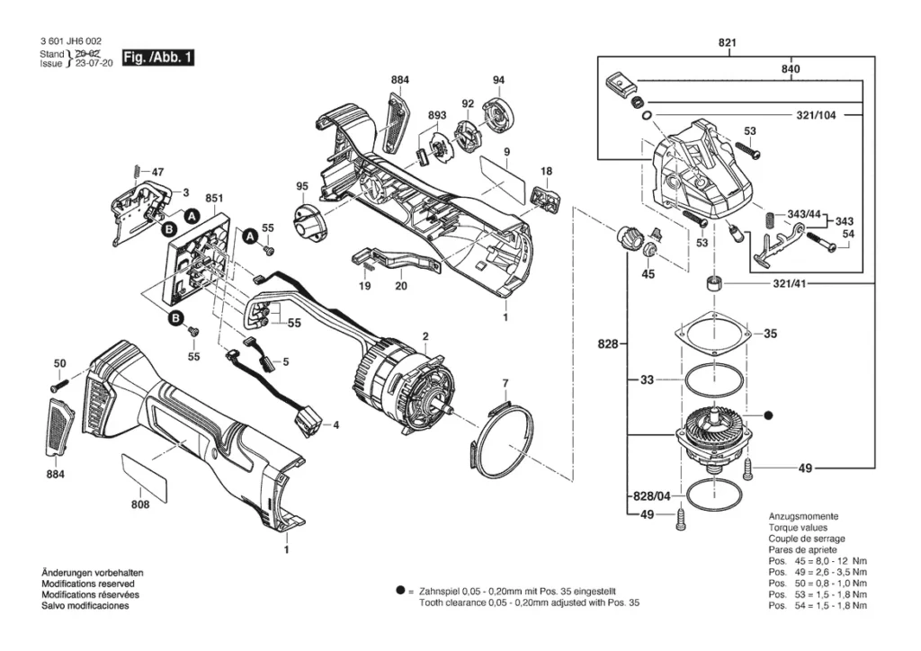
Read a parts drawing by assembly: power supply and switch, motor, gearbox, spindle, accessory mount, then guard and handles. Record drawing revision and part number before requesting a replacement.
| Assembly | Function | What to identify |
|---|---|---|
| Switch and supply | Control electrical input | Switch type; cord rating or approved battery |
| Motor | Convert electrical energy into rotation | Motor design and service part references |
| Gearbox and bearings | Transmit rotation through a right angle | Matched gears, bearing specification and service procedure |
| Spindle and mount | Support and retain the accessory | Thread or locking interface, flanges and permitted accessories |
| Guard and handles | Provide shielding and control | Guard type, attachment points and compatible handle |
- Match spares by model and part number, not housing color.
- Keep an approved parts list with procurement records.
- Ask whether a replacement requires a qualified service technician.
Follow power from motor to wheel
Inside a conventional angle grinder, motor rotation drives a pinion and a mating gear. This gear pair redirects rotation toward the spindle. Bearings support rotating shafts, while gearbox lubricant serves the gear mechanism.
The spindle transfers rotation into a correctly mounted wheel or other approved accessory. Meanwhile, cutting resistance travels back through that assembly. A damaged bearing, loose mount or unsuitable accessory can affect behavior even when a motor still runs.
Keep the diagnosis open. A noisy tool does not automatically need a new motor. Stop using a grinder with new vibration, unusual noise or visible damage and arrange an inspection.
- Describe when a symptom appears: startup, unloaded running or contact with material.
- Record accessory type and model identification.
- Do not dismantle a gearbox unless the service instructions and your qualifications permit it.
For a sourcing discussion, request model-specific assembly information alongside your cordless power tool specification. Do not assume every model shares an identical drive assembly.
Distinguish brushed and brushless motors
A brushed motor uses carbon brushes contacting a commutator. Those brushes wear and may be serviceable, depending on construction. A brushless motor uses electronic switching instead of that brush-and-commutator arrangement.
Brushless construction removes carbon-brush replacement from maintenance requirements. Bearings, gears, cooling passages, switches and electronics still need attention. Motor type alone cannot establish a tool’s service life or performance under load.
Our explanation of brushed motor construction covers brush contact in more detail. For electronic commutation and buying considerations, see the brushless motor guide.
Compare complete tools. Ask for performance results under stated battery, accessory and load conditions rather than accepting a motor label as proof.
- Check whether brushes are user-serviceable or technician-only.
- Request replacement-part availability for the exact model.
- Do not assign a universal operating-hour interval to brush replacement.
Tell spindle locks apart from switch locks
A spindle-lock button holds the spindle for an approved accessory-changing procedure. It is not a brake. Disconnect power and wait for complete standstill before operating it, following your tool’s manual.
A lock-on switch serves a different purpose: maintaining powered operation without continuous pressure. A lock-off mechanism helps prevent unintended switch activation. Paddle and slide switches can have different operating arrangements.
Names matter here. Ask a supplier to identify each control on a sample instead of describing every button as a “safety lock.” Bosch’s angle grinder control overview illustrates several switch and mounting configurations.
- Locate the normal stop control before operation.
- Check that switch behavior matches the manual.
- Never use a spindle lock to stop a rotating wheel.
Match spindle, flange and accessory interface
Threaded-spindle grinders generally use specified backing and retaining hardware. Other mounting systems use a dedicated locking interface. Accessories must match that interface as well as permitted diameter, thickness and operating speed.
A common thread size does not make every wheel compatible. Arbor dimensions, flange shape and guard clearance also matter. Use the mounting sequence supplied for that accessory; do not improvise adapters or enlarge a mounting hole.
Check the whole combination. Before stocking replacement wheels, record which tool models, guards and mounting parts they are approved for.
| Check | Acceptance question |
|---|---|
| Mounting interface | Does the accessory fit the specified spindle or locking system without modification? |
| Dimensions | Are diameter, thickness and arbor within the tool’s approved limits? |
| Speed | Is the accessory rated at least as high as the grinder’s maximum speed? |
| Task and guard | Are the accessory and guard approved for this operation and material? |
Bosch’s accessory and guard guidance explains why diameter and speed checks cannot be skipped. A cutting disc is not a general-purpose grinding wheel.
Keep guard and handle functions separate
The guard helps shield an operator from debris and portions of a rotating wheel. The auxiliary handle gives a second grip point. Neither substitutes for the other, and neither makes an unsuitable accessory safe.
Guard requirements can differ between cutting and grinding. Confirm the correct type and mounting position using the tool manual. Never remove a guard merely to fit a larger accessory.

Inspect the attachment points. A sound handle cannot provide reliable control if its mounting thread or housing is damaged.
- Check guard retention and adjustment before use.
- Inspect handles for cracks, looseness and damaged threads.
- Replace damaged components with approved parts rather than temporary repairs.
Understand cooling, dust control and protection electronics
Motor cooling passages and internal dust-separation features serve the tool. An extraction shroud and a suitable extractor address dust at its source. These systems have different jobs; protecting motor components does not establish adequate protection against inhaled dust.

Some models include soft start, overload protection, restart protection or a brake. Their operation and reset procedures vary. A protective shutdown is a reason to investigate operating conditions, not permission to keep restarting under the same load.
Read beyond feature names. Ask what each function detects and how the operator should respond. Do not assume every cordless or brushless grinder includes every protection feature.
- Keep cooling openings clear using the prescribed cleaning method.
- Use compatible extraction equipment for the application.
- Have respiratory, hearing and other protection selected through the workplace risk assessment.
For wood finishing rather than abrasive metalwork, compare purpose-built power sanders. A speed dial does not turn an angle grinder into a suitable tool for every material.
Check cords, batteries and speed controls
A corded tool needs the specified supply and an undamaged cable, plug and strain relief. Our mains-voltage guide addresses supply selection; it is a separate question from cordless battery-platform choice.
A cordless grinder needs an approved battery and charger combination. Pack voltage alone does not establish compatibility or runtime. Pack capacity, discharge capability, tool design and working load all affect results.
Variable-speed models allow adjustment within a defined range. Select settings from tool and accessory instructions rather than a universal “metal fast, plastic slow” chart.
Keep the rating visible. Missing or unreadable labels make accessory checks harder. Record relevant model and speed information in your equipment register.
- Inspect cables and battery housings for damage.
- Check battery retention and approved pack identification.
- Never rely on a lower dial setting to justify an otherwise incompatible accessory.
Separate routine inspection from repair
Routine checks should identify a reason to stop, not encourage running a damaged tool until its failure becomes obvious. Disconnect power before inspection, cleaning or accessory changes.
A symptom is not a diagnosis. Intermittent operation can have several causes. Replacing brushes without checking switch, supply and other components may miss the actual fault.
| Observation | Next step | Avoid |
|---|---|---|
| Cracked wheel, loose guard or damaged handle | Remove from use; replace or repair according to instructions | Continuing with lighter pressure |
| New vibration or abnormal noise | Stop and arrange inspection of accessory, mount and drive assembly | Assuming bearings or brushes are definitely responsible |
| Repeated protective shutdown | Follow the manual’s troubleshooting and reset procedure | Bypassing protection or repeated forced restarts |
| Worn brushes on a serviceable brushed model | Use specified parts and the approved service procedure | Applying a generic replacement-hour estimate |
Maintain a service record with model number, symptom, inspection finding and parts replaced. For distributor ranges, address spares and documentation during private-label project planning, before customers need after-sales support.
Build a model-specific inspection record
Turn the parts list into a usable record. Keep model identification, manual revision, permitted accessories and service contacts together. Add inspection dates and unresolved faults rather than recording only purchase dates.
- Confirm controls, guard, handles and accessory mounting.
- Keep training and application-specific precautions separate from the parts list.
- Remove questionable equipment from service until its condition is resolved.
CCOHS’s portable grinder safety guidance covers training, inspection, guarding and work-area precautions. Read it alongside the exact tool manual. This anatomy guide does not replace operating instructions.
For a TEBOWO inquiry, send the model number and required component information. Include a label photograph and relevant drawing reference so the requested part or document can be identified.
Frequently asked questions
Is a spindle lock the same as a lock-on switch?
No. A spindle lock holds a stationary spindle during an approved accessory change. A lock-on switch maintains powered operation. Read the manual before using either control.
Does a brushless angle grinder need maintenance?
Yes. It has no carbon brushes to replace, but its bearings, gearbox, controls and cooling passages still require inspection and model-specific care.
Can any guard fit a grinder of the same wheel diameter?
No. Diameter alone does not establish compatibility. Guard attachment, geometry and intended operation must also match the model.
Why does an angle grinder keep stopping?
Possible causes include supply problems, protection activation or a fault. Stop and follow model-specific troubleshooting. Repeated shutdowns should not be dismissed as normal operation.
Can an exploded drawing be used as a repair manual?
No. It identifies assemblies and part numbers but may omit service procedures, adjustments and required checks. Repairs need the appropriate instructions and qualified personnel.